Theory/Function
This illustrated manual covers in detail the proper maintenance techniques of vibratory parts feeding equipment. The use of these machines is increasing all over the world. However, to date, user personnel assigned maintenance responsibilities have not had routine service information at their disposal. Consequently, users of this equipment have hired the manufacturer’s service personnel to handle these routine maintenance problems. This manual is designed to enable user personnel to execute their own routine maintenance.
Many feeder problems are compounded by the user employing improper service procedures due to an incorrect diagnosis of a problem or an erroneous interpretation of symptoms. Properly maintained vibratory parts feeding equipment enjoys a field reputation for relatively trouble-free operation. Consequently, it is the purpose of this manual to provide industrial operators and maintenance personnel a handy guide for servicing vibratory drive units – applicable to new machinery installation and routine operational maintenance.
Essentially, we are concerned with the:
1. theory
2. operation and working conditions
3. maintenance requirements of vibratory units
Basic to this information are the important principles of:
1. isolation
2. electrical supply
3. tightness
4. rigidity
5. tuning
for successful, long term, high performance of the equipment.
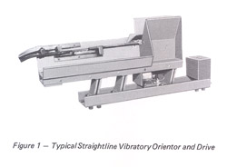
Whether a vibratory drive unit is a linear feeder system (Figures 1 and 3) or a circular one (for bowl feeders) (Figure 2), fundamentally, performance principles are the same. Some units are powered with a rotary electric motor having an offset weight on its shaft while others are air driven with a piston or rotary, off-balance, ball. Still others are driven with a static electro-magnetic coil having the advantage of endurance and solid-state operation.
The basis of an orienting feeder system is the forward movement of a workpiece on a specially prepared surface. A part can be carried along by way of a belt conveyor, but the purpose of moving a part from one position to another may involve more than just its simple transfer. So, as the belt propels the parts, it is usually necessary to include stationary, special tooling to manipulate them in transit and get them oriented for their next use. To achieve this, it is important to design all the unit’s features to convey and manipulate the parts successfully. This is not an easy matter because deformed or “tramp material”, not intended for orientation, can jam between the moving feed belt and fixed orientor tooling, ultimately destroying the whole process. For this reason, some designers believe in the avoidance of belt orienting conveyors and rotating bottom bowls.

A better alternative is a system where the part’s support surface is not moved continually but pulsated. This idea can be visualized by imagining the action of a dish as a tablecloth is suddenly pulled from under it. The dish tends to stay put by its own inertia. Vibratory feeding involves a surface being repeatedly pulled from and reset beneath a workpiece.
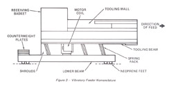
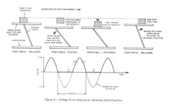
To achieve this, we fit flat springs from the underside of the part carrying surface to a base, which is them isolated from the external environment by coil springs, or rubber-like feet (Figure 3). The system operates by pulling the upper beam (supporting the parts) down and away from the direction of intended part travel very quickly. Owing to the angular positioning of the springs on the unit, and the fact that they are held firmly at the top and bottom, the upper beam moves straight back, but also drops down and away from the workpiece. If this is done rapidly, the workpiece will tend, by its own inertia, to remain in position for an instant. Then, gravity comes into effect to pull the workpiece vertically down to a new spot, further forward, on the upper beam. Hence, with successive movements of the beam (retracting backwards and releasing forwards) on a repeated basis, the part gradually travels forward in a hopping motion (Figure 4).
The top beam can be cycled or rhythmically pulled by a number of methods. One way to achieve this is by utilizing a powered rotating shaft with an eccentric weight secured to the top beam. A second technique uses an air vibrator (which is simply an air propelled ball running around a circular track) to give oscillation to the upper beam. A further method provides the action through the use of an air powered piston. The drive action can also be supplied by extending a steel armature plate from the upper beam and pulling it with an electro-magnetic coil secured to the lower beam (Figure 3). This method, in fact, is the most popular in use today. It is quiet and operates at a much lower cost.
OPERATING AND WORKING CONDITIONS
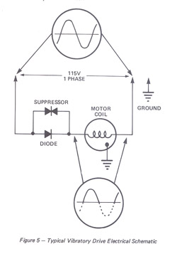
In the United States, the normal power frequency for vibratory feeders is 60 Hertz (60 positive and 60 negative cycles per second) at 115 volts (though other countries may have power sources with 50 Hertz). This means that, for every second, there are 120 possible pulling efforts at 60 Hz. Most find it best to remove one portion of each cycle so that, for half the period of 1/60th of a second, there is one full voltage pulse and nothing for the remaining half (Figure 4). An electronic diode is utilized to achieve the removal of one voltage pulse from each cycle. The diode, through which the standard 115 volt power passes, allows electrical energy to proceed in only one direction. The modified power (it does not matter which pulse is blocked off) is then applied to the drive unit’s motor coil (Figure 5). Installed in parallel with the diode is a suppressor which ensures that power surges (occurring especially when machines are being turned on and off) are not permitted to damage the diode. Without a modified pulse system, the drive unit would have to withstand and react to twice the amount of pulsation, requiring much stiffer springs to move the top beam back before the next pulse and a much heavier total drive structure to achieve maximum efficiency.
An orienting drive needs the positive directional control which flat springs provide. Their stiffness gives direction to the upper beam, so that it cannot float side to side (as with coil springs) to get the greatest efficiency and best orientor performance. For this reason, torsion bars and coil springs are seldom used for quality drives but, instead, flat springs are employed. Most are made of steel, although some have been non-metallic.
Every vibratory drive unit has the following components as standard: A lower beam, an upper beam and a tooling fabrication channel; though they may vary in size to suit orientor length. An electrical shroud, motor coil and spring components are common to every unit, too (Figure 3).
It is necessary on all vibratory feeders, bowl and straightline, that the base be reasonably stationary in order to properly drive the upper tooling channel. Therefore, the bottom beam structure is made substantially heavier. On occasions where tooling and parts become too heavy, causing excess movement in the lower beam, extra weight may be added to the underside of the unit. This is important because correct operation of the machine relies on the weight factor. The action which then results is like a tug of war between two men of unequal size, with the smaller person being moved around, at will, by the larger man.
Whenever the upper beam is pulsed, every element of it must always go in the same direction at the same time. There is a tremendous amount of force fluctuating this upper beam so that when any portion of it, or the tooling, begins to vibrate separately, or out of phase from the remainder (especially unstable tooling), its performance will be dampened or killed entirely. Similarly, if there is contact with an external agent, the unit will be damaged and detuned. Carefully designed and positioned gussets, ribs and struts help to provide maximum tooling stiffness and prevent fatiguing, which is vitally important for the achievement of efficient, long life, drive.
For proper analysis, the maintenance and servicing of vibratory drive units falls into two distinct groups:
1) those that have just recently been put into production; and
2) those that have been in production for more than a few months.
It should be remembered that on all new units which are completely tooled, with orientors, thorough tuning and testing with sample parts has been carried out before shipment. Therefore, no tuning complications should arise unless some form of structural change has occurred in the unit. However, the following test provides a guide to solving initial problems with the unit upon installation, along with maintenance procedures that must be pursued later in its use.
The most frequent problem with a new unit is a lack of isolation. One major area of difficulty occurs where units, previously broken down for shipment, are incorrectly reassembled with their associated tracks and chutes. When feed tracks are utilized, whether they be purchased with the unit or already belong to the user, there must be sufficient clearance from the orientor’s action when it is running at maximum speed. Special care must be exercised in the mounting of the static elevator chute overhanging the orientor receiving basket. There must always be clearance, though the gap should be close enough to prohibit parts from falling to the floor. Thus, this gap will vary according to part size. Also, the static return chute, for transferring misoriented parts back to
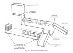

the feeder bin, has to clear the unit’s vibratory motion and yet be close enough to prevent parts loss. As a result, after erection and assembly of the orientor, its elevator and return chutes and feed tracks, a check should be made for the required isolation clearance before starting the feeder (Figure 6). All too often, electrical drops, air and hydraulic lines, and so forth, are fastened to the orientor for the convenience of installing other machines. These inhibit the drive unit’s need for isolation and will inflict costly damage in a short period of time.
-----------------------------------------------------------------------
Isolation … Easiest to check, should always be examined first.
-----------------------------------------------------------------------
Another possible snag with new units involves the isolator feet. It is very important that the whole vibratory machine remain properly isolated from its universe except the support feet. A series of 5/16 inch diameter by 5/8 inch long hex head bolts secure the drive unit to its support structure. Should the feet be damaged, affecting the stability and isolation of the drive unit, they must be replaced. In such circumstances, and where the original bolts have been lost or otherwise become defective, it is essential that only the proper length bolts are used. Casual replacement of the standard 5/8 inch lengths size with extra-long bolts will cause end contact inside the feet and ruin the isolation requirement necessary for proper drive in the unit (Figure 7). It is similarly of the greatest importance to ensure that the structure supporting the drive unit is rigid, too. If the support is weak, it will tend to move instead of the tooling.
OPERATIONAL MAINTENANCE – ISOLATION
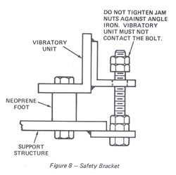
Most feeders have noise abatement components. Those units without noise enclosures have safety brackets which loosely tie the vibratory unit to its support structure. Neither the tie bolt nor its lock nuts must touch the vibratory unit (Figure 8).
With a new machine, there should be no concern about the tightness of the unit’s bolts and the rigidity of its tooling as they are rarely the cause of start-up trouble. However, isolation difficulties are not restricted to new machinery. They may be the cause of performance difficulty with a unit that has been in the field for a time. Therefore, as isolation is the easiest of the concepts to check, it should always be examined first. Where exterior contract evidence is found and corrected, it is likely that some structural damage may have been done (such as broken springs or structural fractures), so the problem may be more deep-rooted. The check for structural damage will be covered later on.
OPERATIONAL MAINTENANCE – ELECTRICAL SUPPLY
Once having made sure there are no isolation difficulties, check for electrical problems. Make certain that 115 volt power is available to the drive unit speed control and out of it. Then, examine the internal electrical supply, involving the electrical shroud, diode and suppressor. The suppressor cannot be easily checked, but since the unit will run temporarily with a faulty suppressor, or none at all (until power spikes destroy the diode), concentrate on the functioning of the diode. Upon discovery of a defective diode, both it and the suppressor should be replaced. A continuity checker can be used to test a diode, and it is essential in such an analysis that only terminal contacts be examined. For a good diode, continuity will be only in one direction (Figure 9).
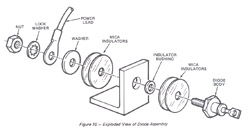
In changing a diode, note that there are two mica washers on either side of its mounting bracket for insulation (Figure 10). A clean surface is required before reassembly when these are changed. If dirt, grit or a burr penetrates the mica discs, it could short the diode.
An insulating bushing, through the hole in the bracket, is used in association with the mica plates. The suppressor and diode, it should be noted, are critically positioned. Also, wires for the electrical system are purposely cut to length and carefully located to limit fatigue. These items are usually mounted on a plate which covers access to the motor coil, although some are sealed inside the speed control box.
Dial-type speed controllers vary power to the vibratory drive motor coil. A variable transformer, by controlling voltage, and therefore speed, offers potentially high power propulsion. Where lightweight and small parts are involved, that do not require a great amount of drive, an SCR speed controller is utilized (Figure 11).
This unit, with a sealed-in diode and suppressor, limits top speed on light duty machines and prevents operators from trying to achieve a harmful maximum drive. SCR controllers are sealed systems (diode and suppressors are not replaceable) which can be beneficial in a plant with severe metal dust or dirt problems. The more powerful, open frame, variable transformer control is always mounted, axis vertical, with a friction drag under the knob to hold speed settings under vibration. Preferably, it should be positioned upside down and under a horizontal surface to shield it from falling debris and dirt. Both controllers include a replaceable fuse.
The electrics have been checked, but drive problems still exist … inspect the tightness of everything on the unit.
OPERATIONAL MAINTENANCE – TIGHTNESS
When electrics have been checked and drive problems still exist, the next step is to inspect the tightness of everything on the unit. It is possible that, after a year or more, the spring pack, counterweight and tooling bolts could become loose. Handling families of parts through an oreintor usually necessitates tooling changes which can result in slackening or loss of these fasteners. Interchangeable or adjustable tooling is designed with enough fasteners to make a secure, rigid system. Designers do not specify quantities of bolts beyond that essential for the effective performance of vibratory machinery. All of the fasteners included in the unit serve some important purpose and the loss or elimination of any of these will detune and eventually harm the unit. It should be made certain that all bolts are in place, torqued to their design maximum and secured with either lock washers, Loctite, or both, at all times.
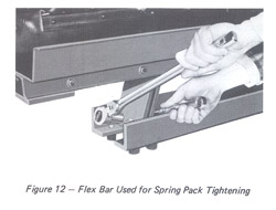
Spring pack bolts should be torqued to 75 foot lbs., as should the counterweight bolts. Such torque cannot be applied with a light duty ratchet wrench, nor can most people apply 75 ft. lbs. with a ½ inch ratchet wrench. A good size man will only generate about 60 ft. lbs. of torque with such a tool. Owing to this, a ½ inch drive flex bar and socket is recommended because it is of the utmost importance that all the spring pack bolts are torqued to specifications (Figure 12).
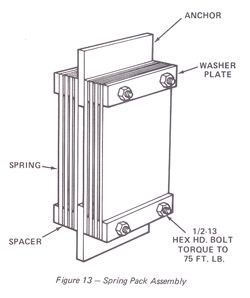
Multiple spring packs are built into all vibratory units, with more on the larger models. Each pack has the same constituents (except perhaps in quantity) and is mounted between the beams (Figure 13). Special, high endurance alloy steel is used in the spring itself. Starting from the anchor, the pack consists of a spring, spring spacer, then another spring, another spacer, and so on; to where the unit is stiff enough to be in tune. Spring spacers are placed between springs, never between the spring and anchor or the spring and washer plate. Without spacers, the springs would abrade each other at the midpoint, resulting in poor tune, excessive wear, fatigue and eventual failure. The installation of washer plates holds the pack solid and provides a constant pressure all the way across the top and bottom of the springs to distribute stresses and avoid strain at the bolt holes.
Spring packs may vary as regards to the number of springs included in them. Once a unit is tuned to adequate stiffness, the amount of springs, per pack, does not have to be exactly equal, but must not exceed the maximum limit, per pack, in the manufacturer’s recommendations. The number, per pack, should be reasonably divided, since it is obviously desirable to avoid a situation where there are six springs in one and two in another. The main concern is that the proper total spring quantity is contained within the system to match the tooling weights.
If a unit has been altered by adding to or subtracting from original tooling weights, it may fail to drive until it is retuned. Increased weight may necessitate more springs in the unit while a weight reduction may demand removal of springs. More on this later.
Any remaining problems with the machine must be associated with cracks in the springs, beams or tooling.
OPERATIONAL MAINTENANCE – RIGIDITY
At this point, we know that the unit is identical in form to the manner in which it was originally tuned and isolation, electrical supply and tightness of the components have been checked. Any problems now remaining with the machine must be associated with its structural integrity, involving cracks in the springs, beams or tooling. A spring pack check should then be made.
The proper procedure to examine springs consists of removing, inspecting and replacing one spring pack at a time, preferably starting at the best point of access. If all the spring packs are withdrawn at once, by the time the unit is reassembled, it could be completely out of line.
Unfortunately, it is impossible to tell if the springs are cracked just by looking at them since, typically, they fatigue along the edge of the washer plate and cannot be observed without first being detached from the unit. A spring may be cracked to the extent that it falls apart when removed. However, hairline cracks cannot always be seen so that some springs might appear to be good when, in fact, they are faulty. To test all springs for cracks, simply drop them from waist high in a flat, horizontal position onto a concrete floor. In this way, a broken spring should fall apart entirely. Where a hairline crack has not penetrated far enough for the spring to fall apart, it will at least have a dead sound when dropped, unlike the ring a good spring gives off.
The springs are made of a special alloy, about 50 percent stronger than mild or regular steel. Therefore, it is recommended that no attempt be made to substitute home-made replacements, as these will be unlikely to last more than just a few hours before they fail. Whenever there is a doubt about a spring, it is always advisable to put in a new one.
Spring packs should not be reinstalled until the anchor pad area is thoroughly cleaned of any dirt and grease and inspected for cracks in the upper and lower beams. Besides this, a check around the inside of the unit, especially around the welds, is easiest to accomplish when the spring packs are out. It is just not possible to simply view a unit and find large cracks in it. Investigation must be carried out very closely, preferably with a flashlight in an entirely cleaned unit. If there is evidence of the orientor tooling pounding on feed track, make a special inspection of the lower beam, around the counterweight base, for cracks.
Once checks have been made to cover isolation, electrics, tightness of the bolts, crack-free drive components and drive is still poor, cracks or lack of rigidity may exist somewhere in the tooling. The unit must, therefore, be inspected further and all tooling components very carefully scrutinized for faults. Normally, tooling details do not fail unless extra strain has been placed on them by external contact. Since the tooling seldom fails in a common pattern, there is no special place to begin an examination. A mushrooming effect at the end of the orientor, created by pounding on feed track, provides a clue that cracks may exist somewhere in the unit. The contact may not be happening at the time of analysis, but mushrooming tells that pounding was done in the past. If this is the case, be assured that cracks, in the unit, are very likely.
Frequently, it is possible to discover pipe, conduit or other foreign accessories secured to orientors in the field. They restrict drive and create excess stress on the units, resulting in crack failures. Cracks will tend to take lines of least resistance and start mostly in high stress areas; around notches, holes and weld joints. Each unit is run-in for about two million cycles before shipment and, in this period, if no cracks or detuning occurs, there will be no failure unless the unit is over-stressed later.
The upper beam and tooling channel, being lighter than the lower portion and having tooling attached to it, is perhaps the most likely to crack first. There are, usually, a considerable number of welds and holes to inspect, particularly around the orientor receiving basket.

Continual parts hitting the basket over the years may split the welds and detune the unit. The receiving basket is often supplied with a urethane liner, and always with a back plate of work-hardening manganese steel, but it can only absorb a few years of heavy pounding before wearing out. The user’s maintenance staff may replace the manganese steel with a ½ inch steel plate which they consider will have a longer life. However, by doing so, they will detune the drive with the extra weight. Sooner or later, all tooling will wear, fatigue and need replacement. Repair personnel frequently substitute heavier materials with the notion that it will give greater endurance. The unit, therefore, ends up with poor performance, unless it is retuned for the extra weight.
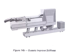
No item of orientor tooling should deflect more than 1/32 inch under thumb pressure of about 20 lbs. of force. If a piece of tooling is found to be too flexible, strengthening is necessary or it will detune, over-stress, and possibly crack adjacent structure (Figures 14a and 14b).
Once it has been set, the motor coil should never move. It works to magnetically attract a steel plate attached to the upper beam and is set with a gap of just 0.104 inch. A spacing of 0.102 inch or 0.106 inch will make no difference. Yet, if the gap becomes too small (say .060 or .080 inch), the coil frame and plate will hammer together, resulting in coil damage and possible cracks in the total structure. False economy directed some vibratory feeder manufacturers to vary the gap for speed control, but only produced severe performance problems.
The preceding represents common problems encountered in our factory servicing. If broken welds and cracks in the unit have been repaired and no changes made to the components of the machine, it should drive correctly. However, too often, users will exchange worn components for improperly substituted new ones and, thereby, add weight to the tooling. It is conceivable that an evenly distributed five pounds of extra tooling weight will not significantly alter the efficiency of the spring packs. Nevertheless, it is likely that an extra ten pounds, or thereabouts, will require the addition of spring stiffness. Consequently, after a unit has been completely checked, repaired and is feeding parts once again, the entire tuning process should be performed to make sure the machine is functioning at its full drive potential.
---------------------------------------------------------------------------------------------------------
To ensure the machine is functioning at its full drive potential, the entire tuning process should be performed.
------------------------------------------------------------------------------------------------------------------------------
OPERATIONAL MAINTENANCE – TUNING
The main purpose of tuning a vibratory unit is to achieve adequate stiffness in the springs to move the weight of the upper beam back at the right moment. Essentially, the fixed pulsing condition of the unit and tooling weight must be matched by spring stiffness. Simply, the heavier the tooling mass, the greater amount of springs necessary; the lighter the load, the fewer the number of springs required. If the springs are of insufficient stiffness to return the beam to its original position, after having been pulled back, then the upper beam may still be returning to its starting point when another motor pulse occurs. Where this happens, the pulses are working against each other and the unit’s action will be damped. The requirements are, therefore, that springs should be added to a vibratory drive unit up to a point just sufficient to bring the upper beam back to where it belongs before being pulsed again. Action is lost when too many springs return the beam too early in the cycle. In the field, then, inspections should be made to see whether heavier tooling or heavier workpieces have been applied to the unit, because without corresponding increases in spring stiffness, the unit’s drive can be killed. Conversely, if changes have occurred resulting in a lighter tooling mass and employment of smaller parts, letting the upper beam return too quickly, the number of springs may have to be reduced.
To carry out a check of the unit, it is very important that everything is tight, especially the spring packs, otherwise the machine cannot be effectively tuned. With the unit on and the speed control set to slowly move the part, loosen one spring pack bolt. It makes no difference which bolt on which spring pack is relaxed, so select one which provides the best wrench access. As the bolt is loosened, the unit will either speed up or slow down. Where the machine slows down, a spring should be added and the procedure repeated; but where it speeds up, one spring should be removed.
It is desirable to have the addition of an extra spring cause a slightly increased speed in the bolt-loosening test, but its removal causes a decrease. Then, where the unit’s vibration is again stepped-up, upon replacing the spring, this is the optimum, perfectly tuned position. If this action does not result, springs should be added until this point is reached – up to the maximum number specified by the manufacture. With any unit that hasn’t had drastic weight change, it should not be necessary to add or subtract more than one or two springs to achieve the desired drive. On occasions where it becomes necessary to add four or five springs to attain maximum drive on an unchanged tooling structure, something is still wrong with the unit. The simple addition of more springs may speed up a sick unit by overcoming cracks or lack of rigidity for a short time, but, in reality, it won’t give long-term performance. Prior to tuning, weak structures must be properly strengthened.
Remember that all vibratory drive units lose speed after a few hours of operation, due to the natural relaxation of springs and other component materials and should, for this reason, be initially over-sprung. In this way, as the machine’s constituents begin to relax, the drive unit will show a slight increase in performance rather than a decline, and it can compensate for the extra weight of parts being carried by the orientor, too. Such an over-sprung unit, of course, will then show a slight increase in speed when a spring pack bolt is loosened.
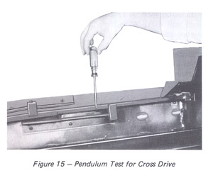
Once the proper spring pack compositions have been worked out for the unit, the next step is to check for cross drive. This can be done by putting prick punch marks at various points on the unit’s top surface and observing the lines they trace. All of them should run straight, parallel with the orientor length. If the lines are running off to one side, or in a circle, unwanted cross drive is present, caused by a lack of rigidity or by the tooling mass being off to one side of the drive unit. Cross drive can most easily be checked when a unit is operating by simply holding a screwdriver or other slender shaft, vertically, and letting it hang like a pendulum while dragging it along the length of the tooling (Figure 15). With normal drive conditions, the screwdriver will only be rubbed by the unit as it vibrates. But, if unwanted cross drive is present, the screwdriver will repeatedly bounce off the unit’s side. This condition will cause parts on the tooling to react poorly and be dislodged. The cross drive problem can be solved by balancing offset tooling with added weights and by stiffening weak tooling structure. Note that a recheck of spring stiffness must be made to correct for added weight.
When cross drive has been eliminated, the trace will be straight and in line with the unit. For a uniform vibratory action over the full tooling length, the upper beam’s center of gravity (including tooling) should be on a line perpendicular to a spring pack and in line with the center of gravity of the lower beam. With a 15 degree spring angle, it is best to get trace lines on the side of the tooling and upper beam as close to 15 degrees above the horizontal as possible for the desired drive action. Obviously, slight variations will not make a great deal of difference to the drive, provided everything else is in order.
A check of the unit’s trace lines can be carried out by prick punch marks at different places on the side of the upper unit. Any mark, under vibration, should form a distinct trace line perpendicular to the springs, even though it may be only 1/16 inch long. Bright spots on screws, caused by wrenches, or elsewhere on the sides of the tooling, similarly, provide easily seen lines of motion with which to check the overall feed action of the tooling and upper beam.
If the orientor discharge end is steep, the removal of counterweights at the rear of the lower beam will serve to correct the situation. Where the conditions are reversed, the addition of counterweights will solve the problem, though a manufacturer may specify certain limitations on the number of weights to be used. Generally, the whole situation concerning trace lines, springs, counterweights, and so forth, will not change on a unit in the field unless there is a drastic change in the mass distribution of the tooling. (Note: Bowl feeders seldom require base counterweights.)
When the unit has been thoroughly examined and determined to be isolated, rigid, tight, electrically sound and slightly over-sprung, there is achieved what is known as tuned frequency performance. The purpose of increasing or decreasing spring stiffness in vibratory feed units is to achieve the peak performance for the specific tooled unit, because a small amount of energy does a mystifying amount of work when operating at the magical natural frequency.
These are the basics of a vibratory drive unit that can be used for parts or materials feeding. The essentials to remember when utilizing the units are the four important elements of : isolation, electrical supply, tightness and rigidity, plus the fact that they need to be properly tuned. With due consideration of theses key operational factors, any unit may be made to perform at its peak.