Parts Feeding
ABSTRACT
During the last fifty years, hundreds of parts feeding concepts have been used to advance automatic production efforts. Most of todays feeder features are improvements of early concepts. Few comprehensive sources of parts feeder technology are available, however. There is, therefore, a need to know of progress in the field to alert users of available technology. Such update information must be tempered by individual project needs and reviewed by competent feeder people for best results. Parts feeder builders having experience with more tricks of the trade are the best source of parts handling solutions.
AUTHOR
Richard D. Zimmerman
President
Spectrum Automation Company
Livonia, Michigan
CONFERENCE
Assemblex VIII Conference
March 16 – 18, 1982
Cleveland, Ohio
INDEX TERMS
Materials Handling
Feeders
Human Factors Engineering
Assembly
INTRODUCTION
The purpose of this presentation is to alert applicators and users of parts feeders to features and conditions, in the industry, that can effect better decisions.
This update on the art of parts feeding is drawn from the personal experience of the author and his associate staff.
Both in-house and field experiences with the sales, design, build, debug and service of parts feeders are the basis of this information.
In-the-field experiences provide update information on those feeder features which are beyond the scope of the writer’s company activity.
Update subjects are principally with new and different uses of the already established art.
ORIENTATION
Rotary, orbital and vibratory bowl feeders have been available for many years. Straightline vibratory and belt conveyor orientors are more recent developments. All have been refined to nearly triple production rates that were thought to be at peak twenty years ago.
Rotary bowls use agitator slots to lift and tumble parts onto a gravity orienting track. Simple parts, at reasonable production rates, are most frequently fed with these units. Noise, parts abuse and tooling wear are good points for critical consideration. Several feeder firms offer rotary bowls for users that prefer them to vibratory units.
Orbital bowls operate with action from a vertical axis, rotating disc within a fixed perimeter wall. Parts are moved to and along the wall by the disc’s friction surface. Tooling, similar to that of a vibratory bowl, gets parts from the disc action. Certain part shapes have been fed at near 1,000 pieces, per minute. Thin flanged parts, thin discs, complex parts and tramp materials do not lend themselves to reliable performance in orbital bowls. Tramp material or a thin part edge can jam in the gap between fixed orientor tooling and the rotating disc. For the many parts that can be fed in this unit, a backup bulk storage unit may be needed to keep up with the high feed rate. A half dozen firms are experienced in this feeder concept, which was developed originally for ordnance assembly.
Vibratory bowls have added tooling features to inspect, sort and even assemble certain parts. Tooling is usually built by artisans, to suit the function, with work hardening stainless steel. Complex helical or spiral tooling cannot be heat treated without shape warpage.
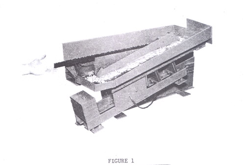
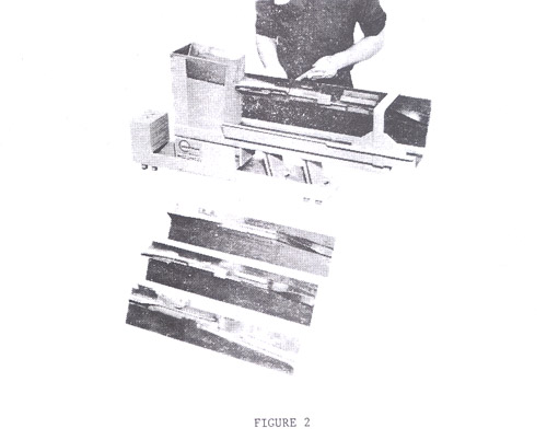
Straightline vibratory orientors (Fig. 1) use the same principal of operation as bowls with some possible extra benefits. In-line orientor tooling permits simplified, true design records for preorient, orient, sort, inspect, distribute to multiple paths and live feed functions. The straightline concept permits quickchange bolt-in tooling plates (Fig. 2) for families of parts. It also permits fully hardened part contact surfaces for long term accuracy and wear life.
Many bowl feeder manufacturers are now limiting maximum bowl size at 18 – 24 inches. Larger bowls are normally applied for larger parts and/or more storage; apparently, a combination that costs too much for noise control.
Large bowl production rates and related storage volumes usually call for a floorbin and elevator or overhead bulk supply unit.
It is seldom cost effective to invest in a new bowl feeder that must have a floorbin-elevator or other bulk backup units. Fully considered, a feeder package consisting of a floorbin-elevator and straightline orientor will cost less than a bowl feeder that needs a bulk supply hopper.
Gravity powered orientation is the least cost method of feeder application as long as the parts are suitable. Some experienced feeder builders have produced units that feed whole families of parts with ease and reliability at competitive prices.
Simple rolling and sliding parts can be gravity oriented off the side of the floorbin-elevator using slanted lift cleats. For certain parts, it is beneficial to carry them over the top of the elevating conveyor, into a gravity trough with suitable tooling.
Only experienced feeder applications people can safely choose gravity orientation as a recommended solution to parts handling problems. Too many poor choices by novices have hurt the reputation of gravity orienting procedures.
As part shapes become more complex and/or production rates go higher, the choice of low cost gravity orientation becomes less safe. Consider recirculation, noise and parts abuse as you evaluate a gravity orienting choice for feeding your parts.
Use experienced feeder makers for functional and economic comparisons of each feeder application.
BRUSHLON®
Recall how a throw rug tends to creep on top of a carpet with normal walking traffic?
Parts are moved by vibratory action, on a carpet-like surface of directionally oriented bristles. Variable angles and lengths of bristles are available to suit part weight and desired feed action.
A small amount of drive vibration is amplified by the bristles’ angle/length action to gain remarkable parts feed rates.
Most vibratory feeder makers have used the bristle carpet material to solve special problems. At least one firm uses the material as a matter of course.
Advantages and/or disadvantages of the bristle carpet feed system are:
1. Quiet
2. Gentle
3. Fast feed rate
4. Light duty drive
5. Limited part shapes, size and weight
6. Material cost
7. Installation cost
8. Dirt build up
9. Cleaning cost
10. Bristle matting
11. Wear life
12. Effect of oil/chemicals
Consider the above list and discuss possible application with experienced feeder people. Proper application success is great but with limitations that must be considered.
SOUND CONTROL
Noise control became a new demand upon feeder makers in the late 60’s. Nearly all feeder concepts were hard pressed to limit sound within OSHA specifications (90 dBa, maximum employee exposure for eight hours). Users with high ambient plant noise required still lower feeder limits to avoid noise accumulation totals exceeding OSHA.
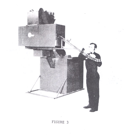
Most feeders were shrouded to contain noise (Fig. 3). Orienting units of high efficiency were developed to reduce excess recirculation. Special surfaces were applied to part contact areas to control noise production.
Stamped metal, engine rocker arms, are sleigh bell-like in noise production. Typical price to limit their sound at 80 dBa was $3,500 in 1980; about twenty-five percent of the whole feeder price.
Fear of Federal regulators caused some feeder users to overkill noise control at great cost. Overkill was probably also caused by political pressure, in 1974, to lower the employee noise exposure limit to 85 dBa. Some feeders were purchased with 75 dBa sound limits, costing more than fifty percent of the whole feeder price.
Limited cast, practical environmental attitudes and cost effective common sense have, lately, done away with much noise control overkill. Eight-five to ninety dBa is becoming, generally, acceptable as standard for a parts feeder noise limit.
Keep in mind that a cost conscious evaluation will allow a feeder to run at higher noise levels for short periods of time. Consider a feeder that runs only a few seconds, per minute, or several minutes, per hour. Should money be spent to control sound at 80 dBa or let it run at higher levels for short periods? This approach could save noise control dollars on low production or high efficiency feeders.
Discuss the aspects of production rate, orientor efficiency, storage track capacity, etc., with your feeder maker for least cost, practical sound pressure control.
FLEXIBLE FEED TRACK
Close wound spring wire tube has been used for years as flexible feed track.
More recently, we have seen high density plastic tube used for the transfer of small parts, air blown, from remote orientors.
Close wound spring wire is now made in rectangular sections for feed track. When coated with adhesive plastic (see Fig. 4), the track may be slotted for visual access, dirt removal and level sensors. Because the part carrying wire is hardened, the wear life is very good while retaining flexibility. Custom made, the product is expensive but often worth the price, compared to other solutions.
A few plastic fabrication specialists will build a mold and extrude lengths of slotted rectangular nylon feed track. Mold cost is high but track is relatively cheap. Some firms have a catalog of available molds which may produce a suitable track section without the purchase of a new mold.
Consider flex track for getting into crowded areas or where a station moves, relative to the feeder. Plastic and plastic coated track will, usually, withstand oils and chemicals but not heat.
FLOORBIN – ELEVATOR
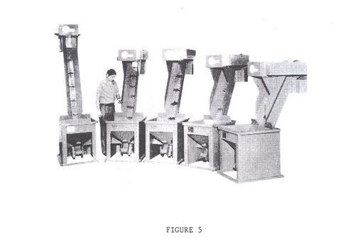
It’s a funnel bottom steel box with an integral elevating conveyor to get bulk parts to overhead manipulators (Fig. 5). Bins are normally available in one to seventy cubic feet capacities. Popular sizes are 3, 6, 12, and 20 cubic feet.
The floorbin must flow parts to the elevating conveyor without tunneling (cavitation) or rolling them. Bin design must allow the conveyor belt to enter its bottom and pass upward without jams; even with complex parts and tramp material.
Elevating conveyor belt designs must pick-up parts reliably without jams. Belts may be fabric, rubber, plastic or steel to suit performance conditions.
Part lift cleats are made of various materials and secured to the belt. The conveyor must be designed to resist jams as parts are moved to final discharge.
Elevating conveyors should be driven at the head shaft by a variable speed motor. Conveyor angle should be shallow enough to pick up and keep parts stable and yet get rid of them at discharge.
Floorbin-elevators provide storage or parts at a convenient service level without ladder climbing or overhead mezzanines.
They are used to flow meter parts to overhead manipulator units such as:
Flow chutes
Manual pickout bins
Weigh and dumpers
Distribution conveyors
Orientor reservoirs
and the like.
For fragile, ferrous parts, an elevating conveyor can be fitted with a plain, non-cleated fabric belt with a magnetic backup.
Most units are built to deliver parts over the top. One exception is where slanted lift cleats coax parts to one side of the conveyor belt against a fixed side rail (Fig. 6). The elevator is very steep to permit part roll or slide to a gravity orientor when the side rail is terminated at a suitable level.
Every part shape is a special challenge to the application of these units. Consult with builders that have made plenty of them to take advantage of there experience.
Nearly a dozen parts feeder makers produce floorbin-elevators with specialty features to serve production automation needs.
RETAINED ORIENTATION AND GENTLE HANDLING
Because early feeder designs tended to damage in process parts, many handling systems avoid bulk storage and reorientation between operations. Some systems use miles of retained orientation track and storage towers with related accessories, at great cost.
Recent developments in gentle handling feeders eliminated the need for retained orientation in the first five operations of making connecting rod caps. Feeders were priced less than half the retained orientation system.
Consider potential simplification and lower equipment cost benefits that could mature from a storage feeder rather than retained orientation between operations.
Many feeder features have been developed for gentle handling delicate parts. One method used a non-cleated, magnetic backed, floorbin-elevator belt to gently remove ferrous parts from the top of the bin load for orientation.
Qualified feeder builders are experienced in applying the best combination of gentle handling features for specific parts. Such features are so numerous and varied that the subject could make a full topic presentation by itself.
BULK DISTRIBUTION
Some manufacturing process systems require feeding parts from a single machine to another operation having more than one machine. Consider bulk storage and distribution to small individual feeders at each process machine.
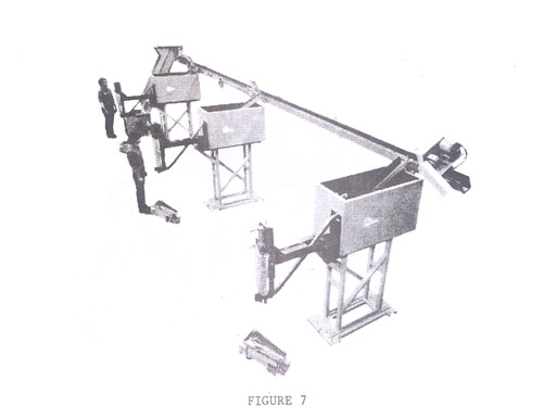
Recent installation proved to cost less for bulk distribution conveyors with individual orientors (Fig. 7), compared to distribution via retained orientation tracks.
Where a family of parts must be fed or a part design change occurs, a bulk distribution system is easily adapted. Changeover costs of retained orientation tracking cannot compete with bulk handling in most cases.
Distribution conveyors, with proper gating, will get parts distributed for orientation at least cost. Conveyor discharge gating design is the critical area in bulk distribution. Don’t use wipers or overhead sluice gates to get parts off the conveyor. Working solutions are available.
HEAVY PARTS
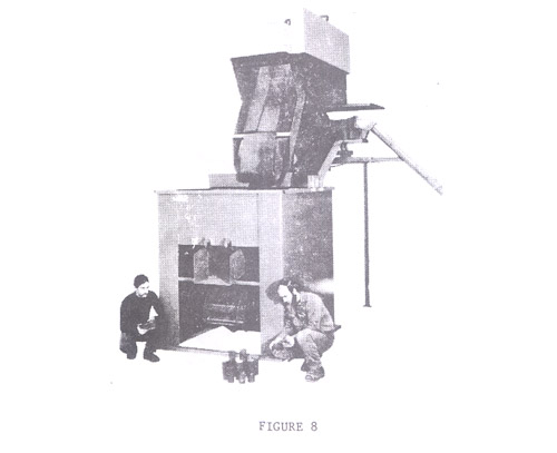
Until recently, most floorbin feeders were limited to handling parts weight of 3-4 pounds. A few feeder models can now meet a ten pound limit. Super duty feeders are also available to orient and feed eighty pound steel billets to forge heaters (Fig. 8).
Heavy, large and complex part designs are now feedable by those who have developed the expertise.
A European vibratory bowl feeder maker has developed a ten feet diameter unit, with a ten feet high center tower to orient and feed steel billets. Part weight limit is near twenty pounds. The bowl’s part storage is limited and somewhat difficult to fill from stock gons. A simple unit costs about $45,000, without noise control. Sound pressure can be well above 100 dBa. Another $30,000 may be needed for a sound enclosure with reasonable stock service access.
Floorbin-elevator feeders, with orienting tooling, can feed up to 80 pound pieces at less than 100 dBa for approximately $60,000, per unit.
Variable features on super duty feeders can greatly affect pricing. Carefully review all project aspects in practical terms with your choice of feeder maker.
TUB DUMPERS
Stock box dumpers are frequently used to get production parts into floorbin-elevator feeders. Most dumpers are designed to get gondolas at floor level and then lift them through an arc by hydraulic leverage or chain drives.
Despite safety gates and interlocks, there have been lift action failures resulting in injury and death.
A few feeder builders offer rotary gon dumpers that straddle a floorbin for reduced floor space consumption. A forklift is used to put the gondola into an overhead rotary cradle (Fig. 9). Should a dump action failure occur, the cradle will rotate and rock to a stand still; rather than drop, as a lift unit can.
Consider the rotary gon dumper for safety and floor space benefits. They are, however, about twice the price of lift units.
Stock box dumpers are used for many subtle purposes other than filling feeder bins. Long parts, shafts or tubes, with length-diameter ratios over 10:1, tend to jackstraw in bulk and resist conveyor pickup for orientation. With a stock box dumper, controlled by a level sensor, parts can be metered to the bin for better production. Jackstrawing seldom occurs where long parts are handled in small bulk quantities.
Elevator pickup action in full, large floorbins can damage parts. A metering gon dumper over a small feed reservoir can assure non-damage handling of parts in smaller quantities.
Stock box dumpers, also, provide backup parts storage.
ROD FEEDERS
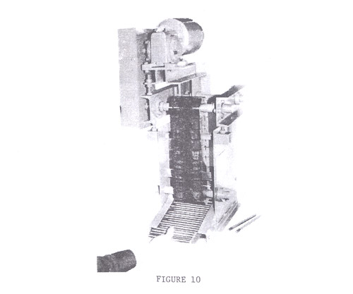
Tubes, shafts and similar shaped parts can be fed with a new device, similar to a toothpick dispenser (Fig. 10).
When diameter/length ratios are less than 50:1, a rod feeder does a good job of metering parts without damage or jackstrawing production delays.
Parts are manually loaded, diameter to diameter, into a bulk reservoir. An agitator meters parts out a stub chute.
Rod feeders can be furnished with adjustable features for parts families of varying diameters and/or lengths.
Normally, parts are longer than the width of a person’s fist, to permit manual loading of the reservoir. A few such feeders have had side access doors for loading short parts.
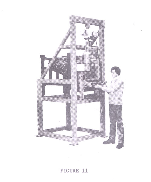
Special, remote loaded, stock boxes can be placed directly into a rod feeder for quick loading (Fig. 11). Only a couple sources offer units to accept remote loaded, insertable stock boxes.
For example; rod feed units have been built for 1/8” diameter by 6” long fragile copper tubes and also for 2” diameter by 36” long sheared steel billets. Paper tubes, for window shade rollers, are fed at more than 100 pieces per minute.
Two kinds of rod feeders are sold and the agitation system is the main difference between them. One style uses cam probes to isolate and roll parts. The other uses continuous motion, rotary sprockets. Continuous motion units are somewhat less expensive and can feed faster.
SUMMARY
Experience and a huge collection of trade tricks are necessary to qualify as a parts feeder builder.
Infinite variations of the described update features are being created and used, to meet the needs of competitive industry, by the parts feeding people.
Choose and get acquainted with a good parts feeding firm. You will profit, far more than they, with properly applied feeders.