Parts Feeding Machinery Concepts
SPECTRUM AUTOMATION COMPANY
Spectrum Automation Company offers you this brief, simplistic description of several feeder concepts with critical comments. It will acquaint you with a variety of parts feeding methods for your best performance choices.
Spectrum has a full menu of parts feeder concepts and over thirty years experience in offering the best of them.
Best feeder concept choices depend upon a full knowledge of the parts to be fed; their design, condition, and environment. That information, coupled with broad feeder experience, is essential to success.
You need the following information before contacting feeder suppliers:
A. Latest part or process print(s) with complete, toleranced dimensions.
B. Three sample parts in their feed condition.
C. Part condition: clean - dirty - dry - wet (fluid?) - dripping (fluid?) - soft - hard - special coatings - residual magnetism - delicate (how, where) - burrs - chips - tramp material (what) - mixed parts.
D. Floor space availability.
E. Height restrictions.
F. Storage required in hours? pieces? cubic feet?
G. Production rate, cycle time.
H. Orientation at discharge.
I. Number of paths, spread pattern, and discharge height.
Here are some facts and comments about feeder concepts for your
parts feeding projects:
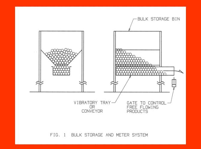
FIGURE 1:
Rising labor costs, larger parts, and higher production rates
called for automatic backup storage of production parts for
orienting feeders. Bulk storage bins of one to six cubic feet
capacity were developed to meter parts, on call, from a sensor,
to typical orientor reservoirs.
A slot in the bin bottom is sized to allow free flow of material to a metering device. Either a conveyor or vibratory trough is activated to flow meter parts to an orientor reservoir. Flow rates are inconsistent, but good enough for a backup supply.
Where parts move too freely, a pneumatic gate is provided to stop the flow.
Normally such bulk storage bins are used to supply the familiar bowl feeder reservoir.
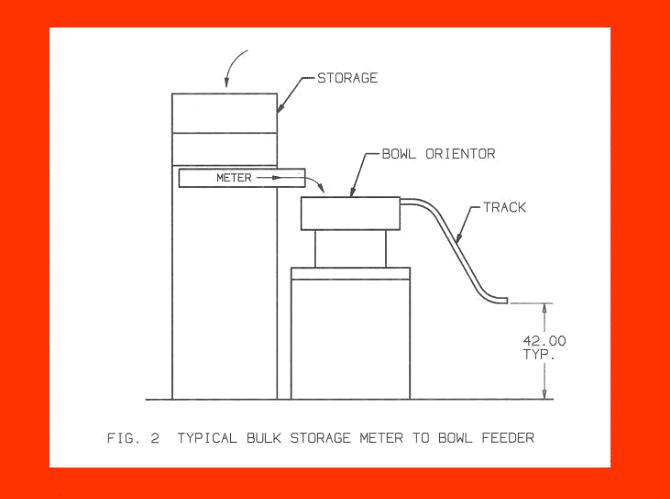
FIGURE 2:
When elevated to suit a typical bowl feeder, the bulk storage bin
rim can be too high for safe restocking. Typical rules limit
manual bin rim service at 30 to 42 inches.
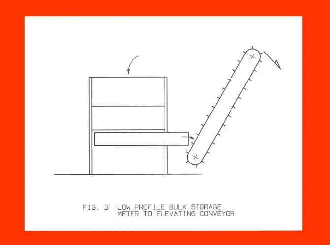
FIGURE 3:
A low profile metering floorbin, with an elevating conveyor,
reduced the rim height. Transfer of parts from the metering
trough to the elevating conveyor created issues of spillage,
jams, and use of floor space.
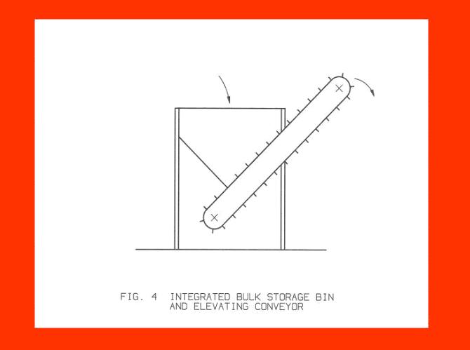
FIGURE 4:
Integrating the elevating conveyor into the floorbin provided
solutions to spillage, jams, and reduced the use of floor space.
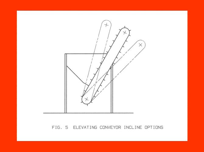
FIGURE 5:
Elevating conveyor incline is open to choice. A shallow conveyor
will move more parts with less fall-back, while taking more floor
space and needing extra support. A steep conveyor saves space and
support structure, but allows more parts fall-back. A balance of
part pickup, fall-back, and floor space use is needed. Spectrum
uses a 60° from horizontal elevator angle as a best balance of
those factors.
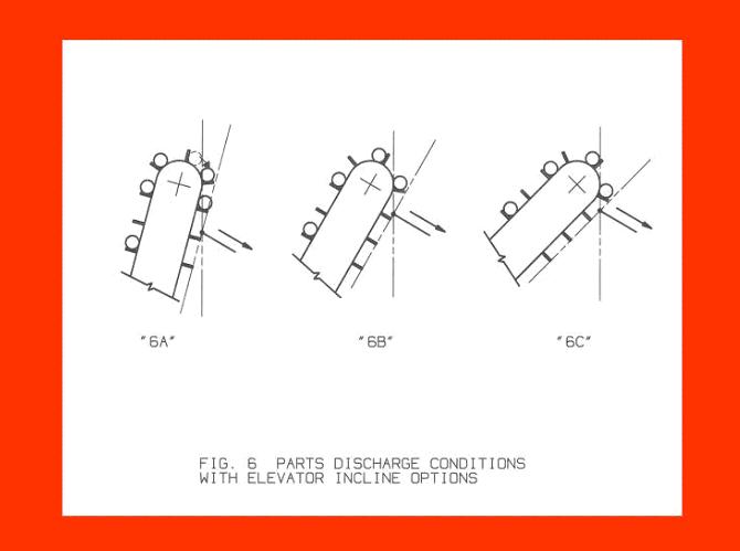
FIGURE 6:
The top ends of over-the-top elevating conveyors, at three
different inclines, show more factors of choice.
Each of the illustrations show a line drawn over the top of cleats on the down-side of the conveyor. Another line drawn perpendicular to the floor and against the top pulley intersects the first line. It defines how close and far up on the conveyor a discharge baffle can be placed. The steep elevator (figure 6A) produces a long drop-to-discharge that will do more damage and create more noise than baffle locations of figure 6B or 6C. Note, also, that steep elevator (figure 6A) will allow a cleat to catch a part from a following cleat. If the back angle of that cleat is too shallow to get rid of parts, there will be performance issues.
Steel will slide, by gravity, on steel at an approximate 28° decline. A good over-the-top elevator angle choice is 30° from vertical. It provides a 30° back angle on typical cleats that could otherwise catch and carry parts down the back of the elevator. Hence, another reason for the Spectrum choice of a 60° elevator angle.
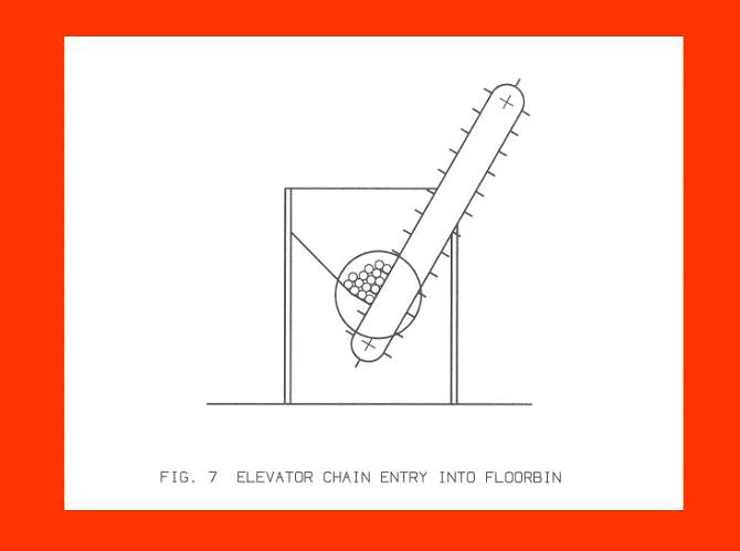
FIGURE 7:
Belt and cleat entry into the floorbin bottom is key to reliable
performance. Parts must not fall out the bottom and yet cleats
must pass into the bin for elevator function. Odd shaped parts
and tramp materials make it difficult to design the ideal belt
entry opening.
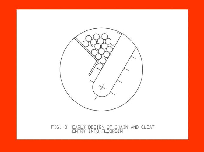
FIGURE 8:
One design attempt for cleat entry into a floorbin is a tunnel
that is a bit longer than the distance between cleats. Parts
variety and lack of force relief cause jam failures in the
tunnel.
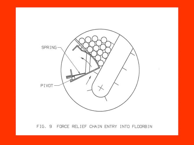
FIGURE 9:
The need for reliable force or jam relief at the bin bottom cleat
entry prompted a hinged plate configured to rise and fall with
cleat passage. Tramp material and parts that reach into the entry
will cause the spring loaded plate to relieve the interference
and reset itself. The plate can be propped open to suit large
parts picked up by small cleats. Where parts are smaller than
cleat heights, the plate is positioned to prohibit parts passage;
yet allow cleat entry. Spectrum uses variations of this feature
on all its floorbin elevators with great success.
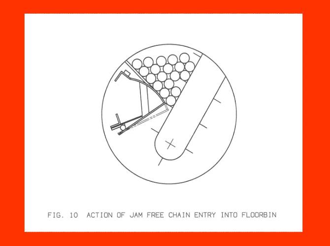
FIGURE 10:
Cleat is shown just before it moves from under the plate which
will close the chain entry opening.
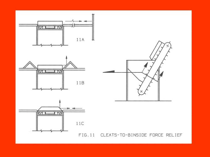
FIGURE 11:
Blocky parts can align and jam between cleat ends and bin sides.
Any sort of interference between cleat passage and parts flow in
the bin must be avoided. Hence, all parts applications must be
evaluated to choose cleat and/or bin bottom features for blocky
parts. Figure 11A shows potential jam force vectors. It is
possible to add force deflectors, as in figure 11B. Note that the
belt rides a bit below the bin plates. Chamfers are put on those
plates adjacent to the belt to deflect similar interferences.
Figure 11C shows 45° end cuts on cleats as another way to avoid
such forces. Parts must be large enough not to fall past end
cuts, through the bin bottom opening. Thirty years and over 5400
feeders has taught Spectrum technicians how to choose reliable
cleat and deflector designs.
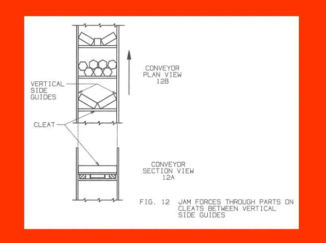
FIGURE 12:
The section view of a typical cleated belt conveyor (figure 12A)
shows vertical guides to hold material in the flow path. Vertical
side guides on any cleated belt conveyor will cause jams when
bulk handling parts.
Figure 12B shows typical part/cleat conditions in a plan view. There is no relief of toggle and wedge part jams between vertical guides.
When a floorbin is designed with the elevator belt recessed in a trough in the bin, the jam potential is greater. The weight of bulk stored parts on the elevating parts increases the chance of jams with vertical side guides.
Too many modern conveyors ignore the vertical side guide issue.
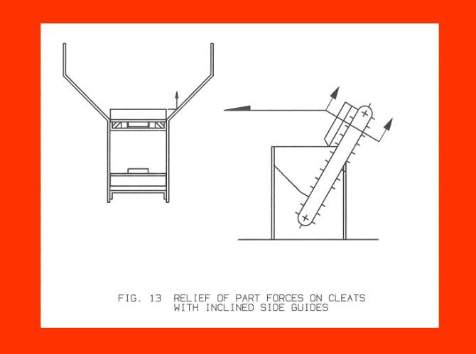
FIGURE 13:
Side guides inclined at 45° offer optimum jam force deflection.
The inclined portion should exceed the longest part dimension to
avoid jams at the vertical segment. Spectrum's conveyor designs
use the 45° side guide wherever bulk random parts are being
handled.
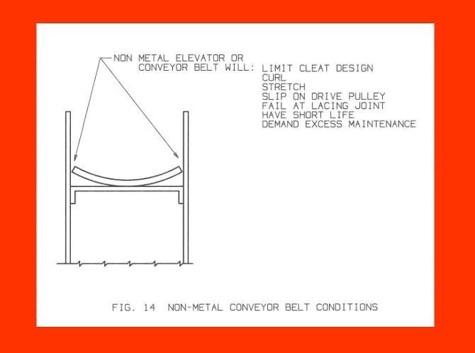
FIGURE 14:
Early conveyor belts were non-metal (fabric, leather, rubber,
etc.) with bolted, riveted, molded, glued, or vulcanized cleats
of simple shapes. Oil, dirt, complex parts, and tramp materials
took their toll on non-metallic belts. Price was low, but
operating costs were high. We, at Spectrum, found that non-metal
belts are not as gentle on fragile parts as you would expect. All
these factors caused a search for more durable and adaptable
belts for floorbin elevators.
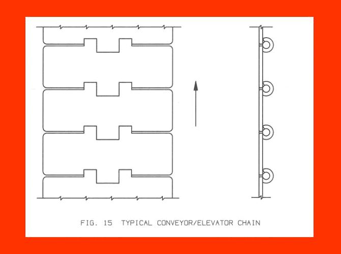
FIGURE 15:
Canneries and bottling operations have used a "table-top" chain
for moving product and containers for decades. Feeder people
discovered its adaptability to floorbin conveyors in the late
50's.
The chain is 1/8" thick, with simple pinned hinges; and available in 3-1/4", 4-1/2", 6", and 7-1/2" widths. The working load limit is published at 600 to 750 pounds. Two makers produce the chain with a non-published strength in excess of 1000 pounds. Recently a stronger, triple hinge, design became available in the 7-1/2 inch width.
The chain is available in delrin plastic, stainless steel, and case hardened steel. Stainless chain is not as strong, but good for FDA regulated products and residually magnetized items. Plastic chain is rarely used for feeders due to its poor strength and cleat mounting issues.
Caution: There are several makers of look-a-like table-top chain. Some do not harden the steel product. Strength and life span are sacrificed for a low price. We recommend the use of Rex and Regina brand table-top chain for best strength and longest life span.
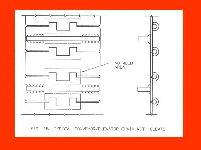
FIGURE 16:
Table top chain of case hardened, low carbon steel permits
careful welding attachment of a variety of cleat designs. Welding
must be done outside the hinge areas to avoid tempering the
hardness and reducing strength qualities.
Bolt or rivet attachment of cleats is discouraged (even with thread lock agents).
Side thrusts on the chain are controlled by guiding the hinge path; not the edges of the chain flites. Work hardening manganese steel (Hadfield Alloy) rails are used in the bin area of Spectrum elevating conveyors.
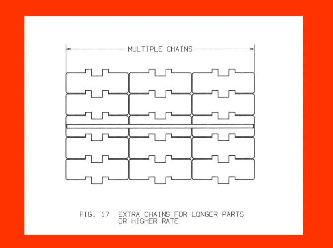
FIGURE 17:
Chain width selection for floorbin elevators is based upon part
size and production rate. Typical small part feeders (up to 3")
use 4-1/2" wide chain. Larger parts (to 6") are applied with
7-1/2" chain width.
As part sizes, cleat designs, and production rates are evaluated, some floorbin elevators employ multiple strands of chain tied together with welded cleats or alignment bars. It's not unusual to use four strands of 4-1/2" wide chain (18") or three strands of 7-1/2" chain (22-1/2") to suit long parts or high rates.
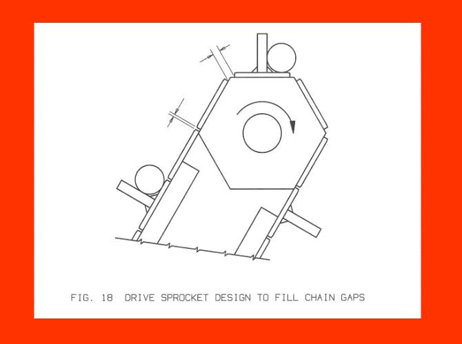
FIGURE 18:
Table-top chain has an approximate 1/16" flite gap and an 1/8"
thickness. There is little concern for part penetration
difficulties when the chain is fully back supported. There are
chain flite/cleat modifications available to handle spark plug
shells with side wires or thin flanged products.
When table-top chain moves over the top sprocket, its normal 1/16" flite gap opens to approximately 1/4". A hexagonal sprocket companion was developed by Spectrum to fill the enlarged gap and avoid penetration of parts or tramp material.
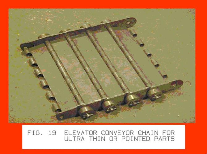
FIGURE 19:
Sharp pointed products such as nails, wood screws, etc., are best
handled in a floorbin elevator that is specially fitted with this
chain. The flites are piano hinged and fitted with moving side
guides that are precision cast for tight fit. A variety of sharp,
thin products are reliably elevated with welded steel cleats on
this more expensive chain.
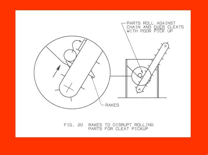
FIGURE 20:
Some ring or disc shaped parts tend to resist elevator cleat
pickup. They align themselves in a face to face, horizontal axis
attitude in the bin and roll over the cleats. Normally, cleats
are designed to pick them up laying flat on the chain.
To pick up rolling parts, cleats must be high enough to get under the part's center of gravity. Such a cleat height could create other performance issues. Hence, a rake or slicer blade of proper height, secured to the chain, will break up rolling part groups for pickup by typical cleats.
A slot in the bin bottom force relief plate allows passage of rakes in one of every 20 to 25 Spectrum feeders.
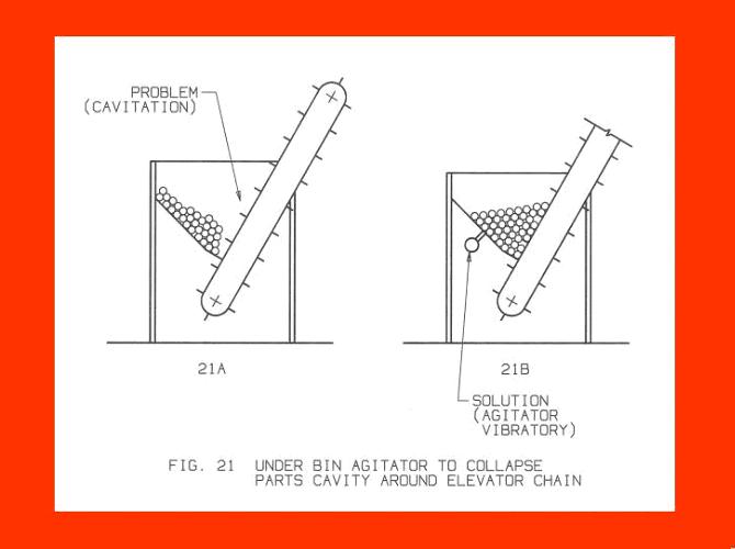
FIGURE 21:
Certain part shapes and materials tend to lay in the floorbin,
resisting flow to the cleated belt. It's called tunneling or
cavitation when bin stock won't flow to the chain (figure 21A).
Larger cleats and/or rakes will only create a larger tunnel.
An underbin vibratory agitator (pneumatic or electrically powered) mounted at the end of a structural arm, will collapse nearly all parts tunnels and assure production (figure 21B). This feature is used in about one of every 50 Spectrum feeders. When the bins get polished by part action, the agitator is usually no longer required.
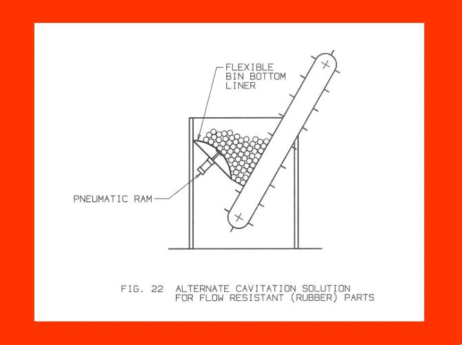
FIGURE 22:
Flexible rubber type parts may not react to vibratory agitation
to cure cavitation. In that rare case a flexible bin bottom liner
is repeatedly pulsed by a pneumatic ram to resolve the issue.
The ram shaft, without a bin liner, will easily enter to agitate the parts, but will experience severe resistance to withdrawal. The parts will work like a Chinese finger cuff on the ram. Keep this factor in mind for a later concept issue.
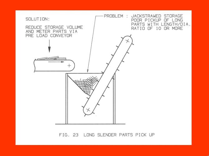
FIGURE 23:
Long shafts or tubes (exceeding 10:1 length/Diameter ratio) in
large volumes will "jackstraw" and resist elevator cleat pickup.
Wider elevator chain will improve pickup, but the issue of
erratic, poor pickup will remain.
One solution to long shaft-like part pickup is to reduce storage volume to just a few dozen parts. They will tend to align themselves horizontally at the bin bottom, parallel to the chain face for easy pickup.
A horizontal metering conveyor can be employed to satisfy a floorbin sensor to maintain a working level of parts that is small enough to avoid jackstrawing.
Knobs, heads, and flanges on shaft-like parts will reduce or eliminate jackstrawing concerns.
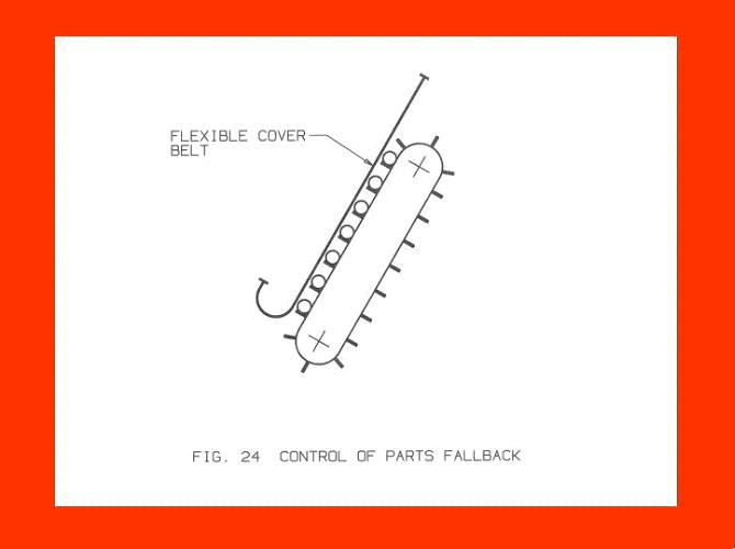
FIGURE 24:
Once parts are picked up, a flexible cover belt will help to
control fallback. A belt that just exceeds the elevator chain
width will coax dislodged parts onto subsequent cleats to avoid
fall-back, noise, part damage, and safety issues.
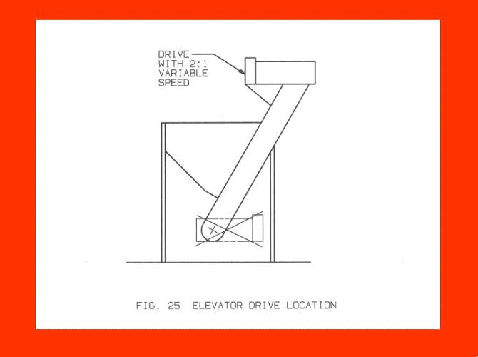
FIGURE 25:
Early floorbin elevators had under-bin drives that pushed
flexible belts or chains into the load of parts. Feeder
performance was severely compromised by the drive location fault.
Be sure that conveyors are head shaft driven for optimum performance and low operating costs. Pull, don't push a belt or chain.
Use a 2:1 manual variable speed drive for production rate tuning.
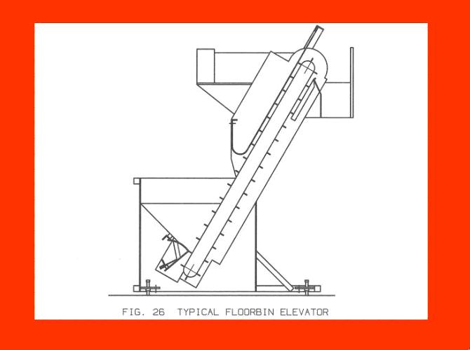
FIGURE 26:
A broad variety of design features contribute to an adaptive,
reliable, functioning floorbin elevator. Those features,
developed by Spectrum experiences, enhance total performance.
To this point, the floorbin elevator has been described to discharge parts over-the-top to reservoirs.
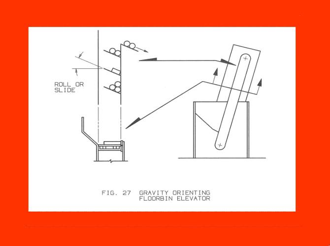
FIGURE 27:
The basic elevator concept is modified to orient simple rolling
and/or sliding parts at a cost advantage over other methods.
A steeper elevator incline (approximately 75°) will allow parts to roll or slide off one side from angled cleats to static tooling. Deletion of one inclined side guide and adding a part retention rail completes the concept change.
Once parts leave the chain/cleat action, only gravity moves them through simple static tooling.
Cautious cleat and orientor tooling designs, by Spectrum, can handle families of simple rolling or sliding parts at reasonable rates.
The cost advantage of gravity orienting floorbin elevators begins to diminish with the addition of plungers, wheels, air jets, etc., to coax gravity powered parts into final oriented isolation.
When parts require face or end selection, recirculation to the bin can reach 70 percent. Noise, abuse to parts, and feeder damage are serious issues for not-so-simple orienting efforts.
Cautious application of the gravity orienting concept can pay extra dividends with low cost performance. Spectrum offers this concept when parts information confirms unconditional success.
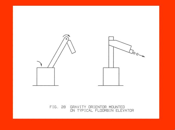
FIGURE 28:
Where parts are adaptable to the gravity orienting concept but
require high production rates, an over-the-top floorbin elevator
can be employed.
Parts are metered into a gravity trough and move through static orientor tooling to assure high rates with Spectrum tooling.
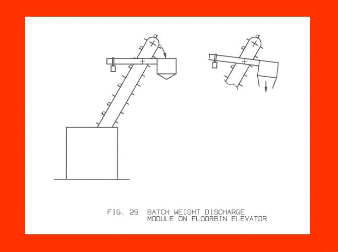
FIGURE 29:
Elevated parts are accumulated in a receptacle until a weight
sensor signals satisfaction. The elevator stops until parts are
bulk discharged from the module to a variety of applications.
Heat treat and plating basket filling are typical Spectrum
applications.
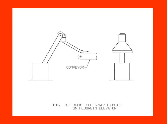
FIGURE 30:
Bulk elevated parts can be spread onto washer, furnace, or
inspection conveyors at a controlled width and depth to match
production needs. When parts backup into the spread chute, a
sensor signals satisfaction to stop the elevator. Gravity flow,
out of the chute, follows the conveyor until the sensor calls for
more parts.
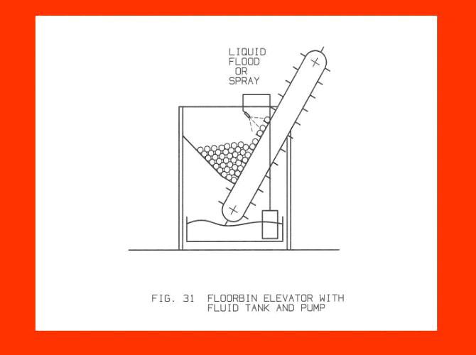
FIGURE 31:
Floorbin elevators can be submerged into tanks and run with fluid
sprayed or flooded on parts as they are raised to discharge.
Similarly, a tank can be placed under the elevating conveyor with a fluid pump and plumbing to flood or spray elevating parts.
Fluids are used to quench, wash, rust proof, lubricate, etc., with this Spectrum custom feeder concept.
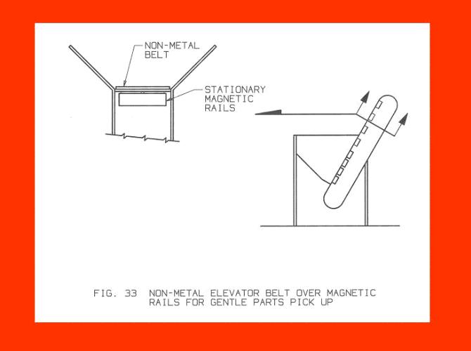
FIGURE 33:
Another gentle handling elevator system uses a non-metallic belt,
sliding on a stainless steel bed. Magnetic rails attract and hold
ferrous parts for a ride to the top. Concentrated magnets in the
bin attract parts. Magnetic rails are made weaker above the bin
to control parts flow. Belt speed is used to tune the rate. A
magnetic head shaft pulley keeps parts on the belt until they are
over-the-top for discharge.
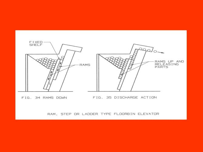
FIGURE 34 & 35:
This floorbin elevator concept does not use a conveyor. Instead,
a set of rams oscillate to carry parts, in stages, up to
discharge.
The rams can be of any width to suit bin and part size for production rate. Ram thickness is selected to pick up parts in the same manner as cleats on a conveyor belt.
The lower ram retracts to the bin bottom and then elevates parts to spill onto a fixed shelf. Parts flow from the shelf to a second ram for a final elevation stage to discharge. Both rams work in unison in this stepping elevator concept. Multiple ram stages are used to gain extra discharge height.
The ram, stepper, step ladder, or ladder concept does an efficient, quality job of elevating parts at reasonable rates. Early models of substantial width were built to deliver parts onto washer and furnace conveyors at a reliable rate, spread, and depth.
More recent uses of the revived ram concept discharge small parts to orientor systems.
Tramp materials can penetrate the close fit of ram slides and cause concept performance issues. Rams operate between fixed vertical side guides which can create toggle jams, as with a chain elevator.
Recall the early concept of ram penetration and faulted withdrawal from bulk parts in a bin. The retracting action of the lower ram in a bin of parts can cause similar stress on the parts and feeder components. Hence, Spectrum is reluctant to produce this newly revived "gentle" handling concept.
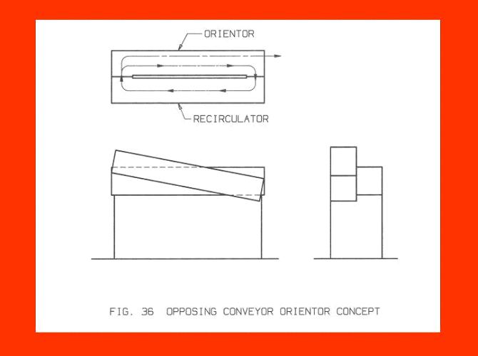
FIGURE 36:
A pair of side-by-side, near horizontal, conveyors running in
opposite directions are used to store, meter, and orient parts.
The concept moves parts in a rectangular flow path until they are
accepted by the orientor tooling.
Flow path features are used to coax parts into an attitude for orientor acceptance. Orientor tooling is normally static, but, cams, probes, plungers, and wheels are used to enhance performance.
Depending on the application, conveyors can be equipped with non-metal belts, table-top plastic, or steel chain and/or heavy duty steel slat chain.
Delicate polished piston pins employ conveyors with fabric belt and plastic table top chain for assured performance, without parts quality sacrifice. This concept uses 48 to 60 inch conveyor lengths.
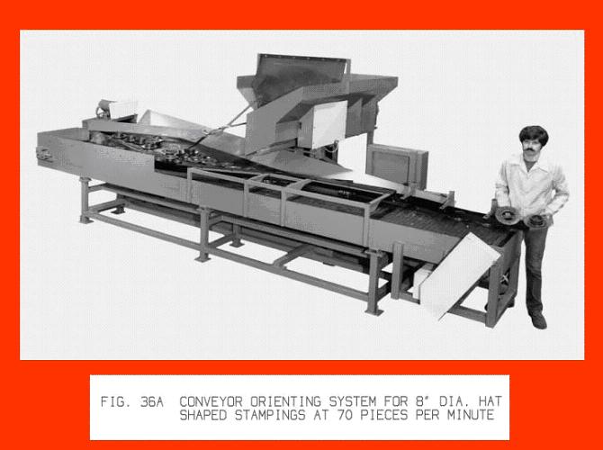
Automotive connecting rods or bearing cap cluster forgings require the combination of heavy steel slat chain for recirculation and steel table top chain for orienting. Such concepts (Figure 36A) can reach lengths in excess of ten feet.
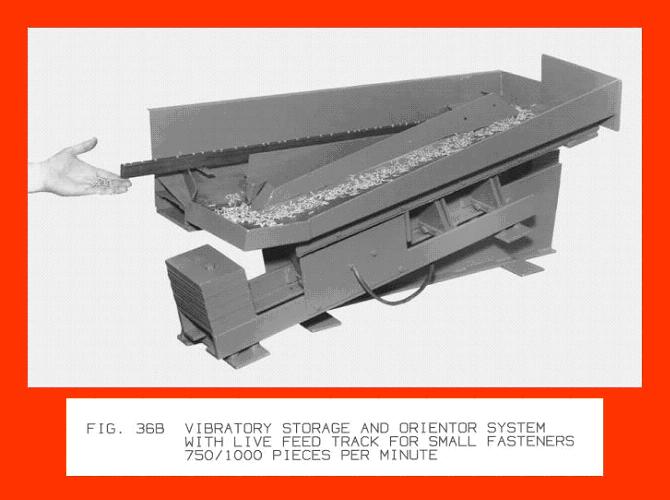
A combination of conveyor recirculation and straight line vibratory orientor units (Figure 36B) are common concept adaptations. They can be as short as 36 to 48 inches with complete reliability.
Conveyor orienting tooling does not enjoy the forgiveness of vibratory action. When complex parts are tried with conveyor orienting, faults become severe jams. Spectrum chooses final concepts to match the parts being handled to avoid unforgiving performance faults.
Storage reservoirs are normally limited and require backup stock features.
Gentle handling, high rate, and quieter operating conveyor orienting systems must be selected with caution.
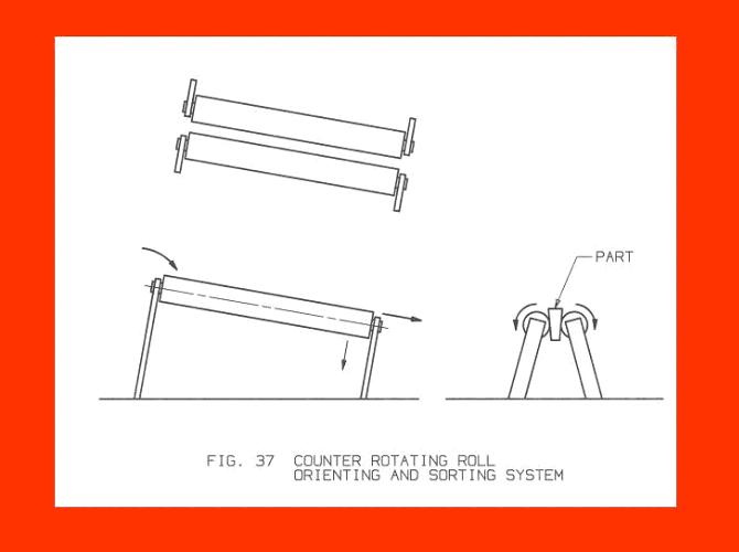
FIGURE 37:
A pair of counter-rotating shafts can be aligned with a
separation gap to accept and flow parts between them. The action
of moving on a decline permits orienting and/or sorting of some
products from a metering reservoir or device.
When the shafts are set with their axes diverging, in the down flow, size sorting can be done. Smallest sizes will fall from the rolls near the top of action. Gradually all parts will fall through at specific size points for collection. Largest or over size parts can be collected as they flow out the end of the rolls path.
Shallow tapered parts, such as bearing rollers, would normally wedge between fixed orient/sort tooling rails. The counter rotating shafts prohibit wedge jams and promote effective orienting and/or sorting action.
Shortest rolls for normal application are 12 to 18 inches. Longest rolls, used to sort ceramic tumbling balls, were eight feet.
Hardware and fastener makers use Spectrum 48 to 60 inch long roll sorters to get rid of mixed items in contaminated product batches.
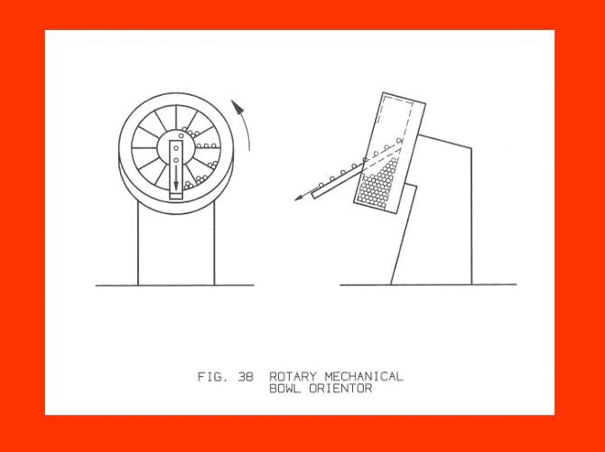
FIGURE 38:
Long before the vibratory bowl feeder was developed, small parts
were stored, oriented, and fed with motor driven rotary bowls.
Their reservoirs held several hands full of parts that were agitated by a slotted back plate, to flow onto static orientor tooling. Misoriented or surplus production parts spilled back into the reservoir in a churning action. Bowl diameters ranged from 12 to 36 inches. Rotary bowls damage parts, cause rapid tooling wear, and create substantial noise. Few are used today.
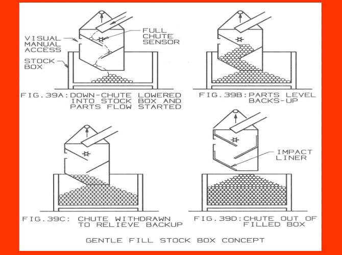
FIGURE 39:
Suspended from a simple hoist or winch, this rectangular chute is
baffled to get parts down into stock boxes without quality
sacrifice.
To establish the baffle drop distance, a test is preformed with a pair of parts by increasing a drop distance between them until damage is noted. The selected baffle drop dimension is less than the damage drop.
Baffles and other impact surfaces in the down-chute are lined with bolted-in durable plastic.
As the lowered chute becomes filled, a sensor calls for retraction increments to allow gentle out-flow of parts into the stock box. Many variations of this concept have been developed and pioneered by Spectrum.
This concept is far more reliable than a manually positioned impact plank in a stock receptor.
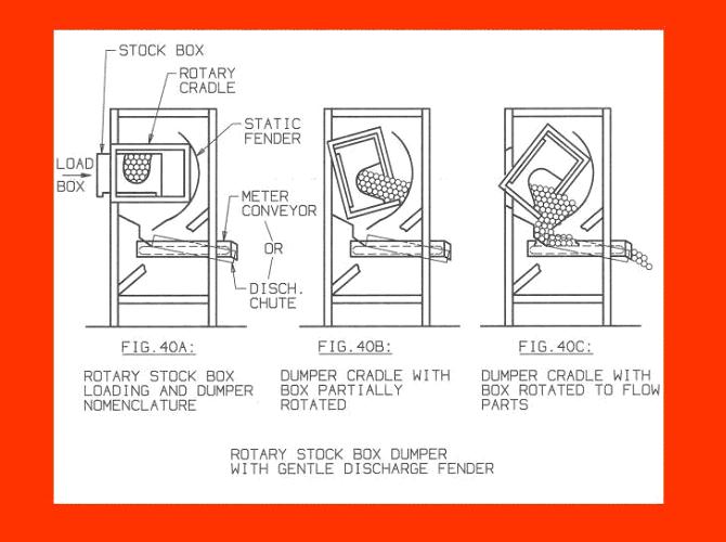
FIGURE 40:
A rotary cradle accepts stock boxes from a typical fork lift
truck. It's normally used to get parts into a floorbin elevator.
Parts can, also, be dumped onto an indexing horizontal conveyor
for metering to a reservoir.
Dumping of stock boxes can be done without loss of parts quality. A rigid fender is used to hold parts in the stock box through most of the dump cradle rotation. The fender terminates where parts will flow from the stock box to experience a controlled drop distance.
The fender feature, introduced by Spectrum, controls noise and parts damage.
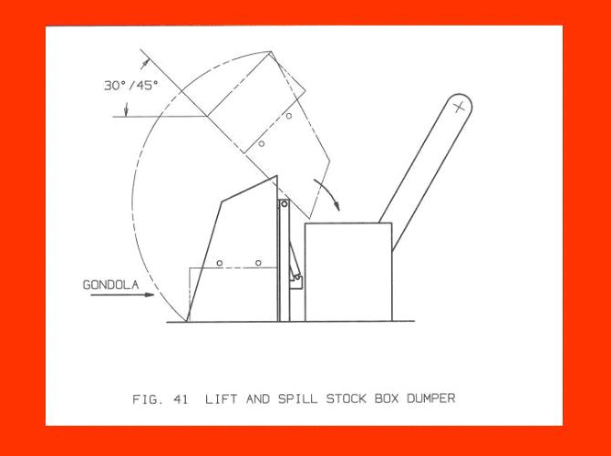
FIGURE 41:
Lift and spill stock box dumpers are lower priced than rotary
units.
Noise created by dumping action is best controlled by a complete enclosure, which will also guard dumper action. Without guarding, the concept is very dangerous. A failed lift can drop the box and cradle with such force that anchor bolts could shear, causing a violent machine shift.
Use extra caution when planning to use a lift and spill dumper to reduce cost. Safety issues preclude Spectrum participation in this product line.
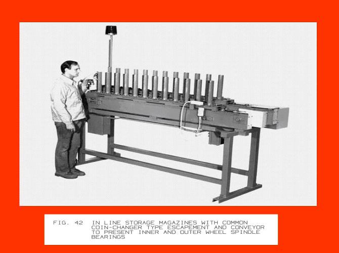
FIGURE 42:
Some fragile parts can be received pre-stacked in tubes for
manual transfer into stock magazines for auto feeding.
A series of vertical, gated, magazines will accept parts like bearings, rings, discs, etc. for a full shift of storage. A coinchanger type escapement releases parts, one-at-a-time, from the magazines for process or assembly.
Frequently, such storage magazines are positioned on a dial index table. An escapement removes parts from one magazine until empty. The dial indexes and another magazine is positioned over the escapement.
A less complex, easier to load model positions the magazines in-line over a conveyor. A single multi-path escapement releases one part at a time from all magazines, at once, onto the conveyor. Parts are conveyed to a sensor monitored pickup point or track. This is an exclusive Spectrum time proven concept.
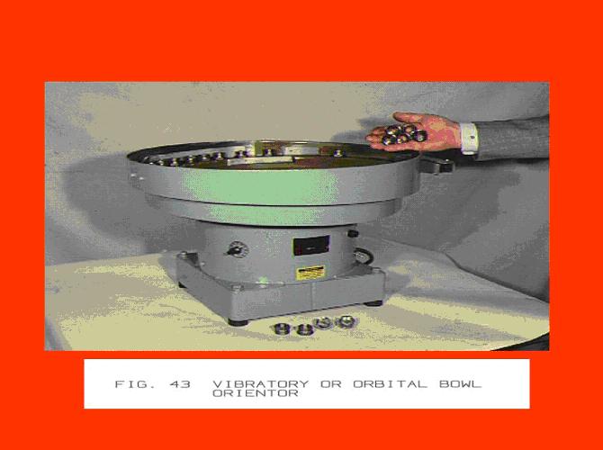
FIGURE 43:
The vibratory bowl is the most popular parts feeder.
They successfully handle parts of complex shapes and different materials.
Vibratory feeders are composed of an upper mass with orientor tooling and a heavy base, coupled by leaf springs. Set radially, the springs create a circular flow of parts up an inclined path on the bowl. A static drive motor, normally electromagnetic, is used to agitate the upper structure and move parts through orientor tooling.
Specially fabricated tooling features are located on the vibrating part pathway to reject or dislodge parts that are not in the desired attitude. Other features are used to coax parts into the required orientation.
The vibratory bowl is effective with most small parts, generally limited to a four ounce weight, three inch diameter, and six inch length. Jam forgiving vibratory action and compact size are the bowl's main benefits. They are usually available in 4 to 48 inch diameter sizes. Bowl size is selected to be ten or fifteen times the largest dimension of the part to be fed. Storage volume is less than 25 percent of apparent bowl capacity.
Another bowl feeder concept uses a tipped axis, motor driven disc bottom to feed parts at very high rates. The concept is expensive and best limited to simple light weight parts.
The rotating disc does not offer the jam forgiveness of a vibratory system. When parts or tramp jam between tooling and disc, the drive is compromised as in a conveyor orientor.
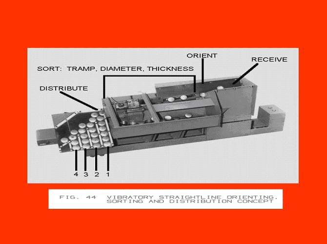
FIGURE 44:
The Spectrum straightline vibratory orientor concept allows more
parts feeding technology in a single system.
Whether straightline or bowl type, vibratory feeder operating principles are the same.
Straightline feeder spring packs are set in-line to create a linear movement of parts through tooling, that can be set on a decline to get extra feed rate.
A single straightline vibratory orientor, by itself, does not have storage capacity. Parts must be metered to its reception area where they proceed through subsequent tooling. Surplus production and misoriented parts must be carried back to the orientor reception point by a storage and return system, such as a conveyor or floorbin elevator.
Even at fast rates, a straightline orientor handles, only, a few parts at any moment, resulting in lower noise levels and reduced tooling/parts abuse.
Typical straightline vibratory drive units are made in 36 and 48 inch tooling lengths. Drive units are paired side by side under heavy orientor tooling for large parts. They are also used in tandem where tooling length exceeds 48 inches for preorientation, orienting, sorting, distribution to multi-parts and/or live feed track.
Designed, bolted-in, hardened steel tooling is typical for the Spectrum straightline feeder concept.
Straightline units can be furnished to accept quick-change, bolt-in orientor tooling plates for families of parts.

FIGURE 45:
Similar to a toothpick or drinking straw dispenser, tubes and shafts can be manually stacked in a reservoir and metered to discharge.
An agitator belt meters parts to exit rolling, via a stub chute. Where parts exceed two inches diameter, a metering ram may perform the agitation effort.
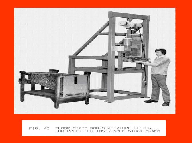
FIGURE 46:
Open framed Spectrum shaft feeder units are built to receive
pre-loaded, specially designed stock boxes to avoid manual
loading. An extra feature is added to open the stock box gate to
get parts to the agitation device.
Families of parts diameters and lengths can be accommodated by Spectrum designed rod, shaft, or tube feeders.
Rod feeders are the best solution to jackstrawing of bulk random parts, where pre-stacking is feasible.