We provide a comprehensive overview of various parts feeder concepts, leveraging over thirty years of experience to help you choose the best method for your needs. The optimal feeder choice depends on a detailed understanding of the parts to be fed, including their design, condition, and the environment they operate in. Essential information to gather before contacting feeder suppliers includes part prints, sample parts, part condition, floor space, height restrictions, storage requirements, production rates, orientation, number of paths, spread pattern, and discharge height.
Feeder Concepts
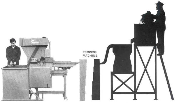
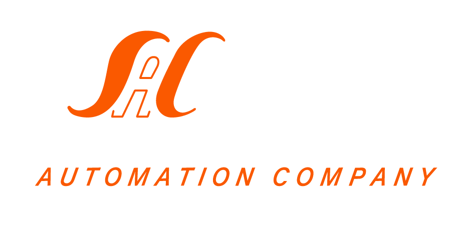
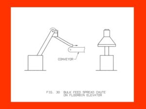
- Bulk Storage Bins (Figure 1):
- Purpose: Store and meter parts to orientor reservoirs.
- Operation: A slot at the bin bottom allows parts to flow to a metering device (conveyor or vibratory trough).
- Issues: Inconsistent flow rates, potential need for a pneumatic gate.
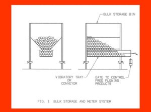
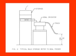
- Safety and Accessibility (Figure 2 & 3):
- Problem: Elevated bins can be unsafe for manual restocking.
- Solution: Low profile metering floorbins with elevating conveyors reduce rim height but introduce spillage and jamming issues.
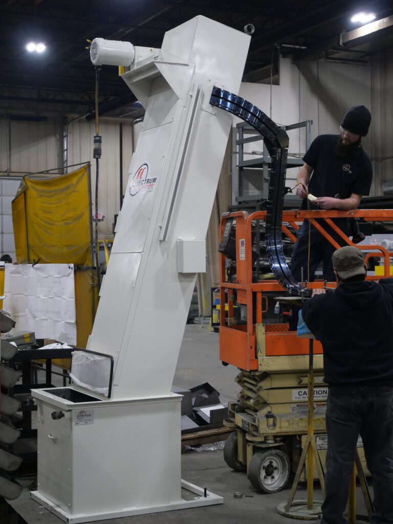
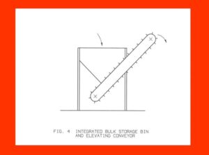
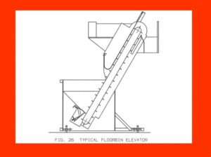
- Integrated Elevating Conveyor (Figure 4):
- Solution: Combines elevating conveyor with floorbin to prevent spillage and jams.
- Solution: Combines elevating conveyor with floorbin to prevent spillage and jams.
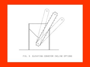
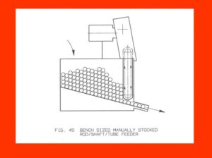
- Conveyor Incline (Figure 5):
- Considerations: Shallow incline reduces fall-back but requires more space; steep incline saves space but increases fall-back.
- Considerations: Shallow incline reduces fall-back but requires more space; steep incline saves space but increases fall-back.
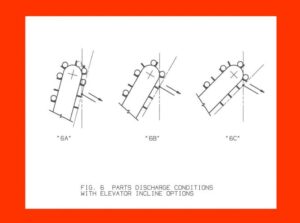
- Elevator Angle (Figure 6):
- Optimal Design: Spectrum recommends a 60° elevator angle to balance part pickup, fall-back, and floor space use.
- Optimal Design: Spectrum recommends a 60° elevator angle to balance part pickup, fall-back, and floor space use.
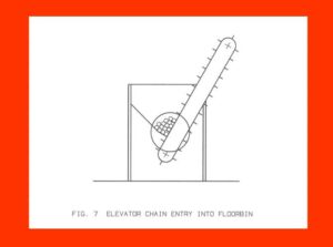
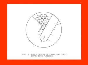
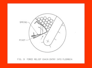
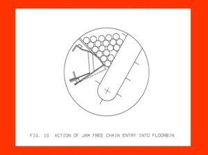
- Cleat Entry and Bin Bottom (Figure 7-9):
- Challenge: Designing reliable cleat entry into the floorbin.
- Solution: Hinged plates for jam relief and force deflection.
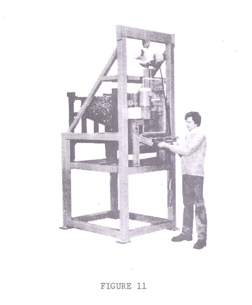
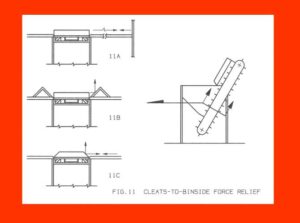
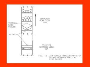
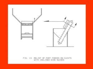
- Jamming and Force Deflection (Figure 11-13):
- Problem: Blocky parts jamming.
- Solution: Use of force deflectors and inclined side guides to prevent jams.
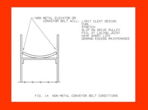
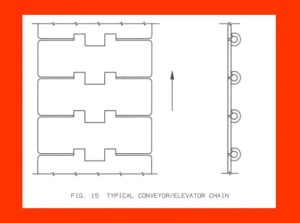
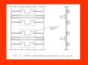
- Material and Cleat Design (Figure 14-16):
- Evolution: From non-metallic to durable steel chains.
- Recommendation: Rex and Regina brand for best strength and lifespan.
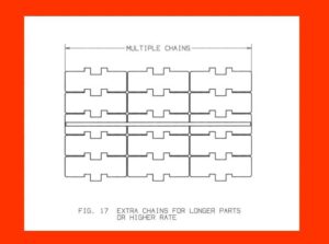
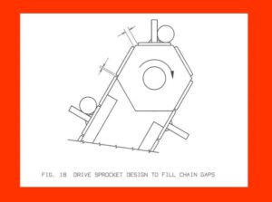
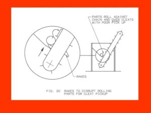
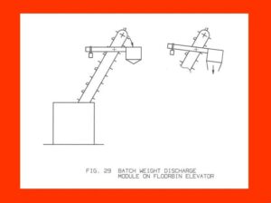
- Production Rate and Cleat Size (Figure 17-20):
- Consideration: Match chain width and cleat design to part size and production rate.
- Feature: Use of rakes or slicer blades to break up rolling part groups.

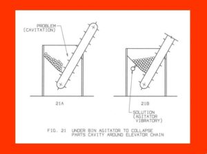
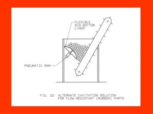
- Agitation and Cavitation (Figure 21-22):
- Solution: Use vibratory agitators or flexible bin bottom liners to resolve parts tunneling.
- Solution: Use vibratory agitators or flexible bin bottom liners to resolve parts tunneling.
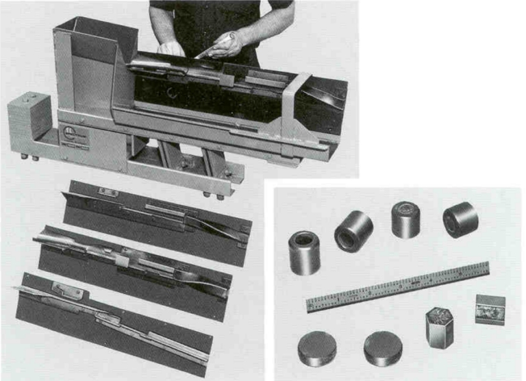
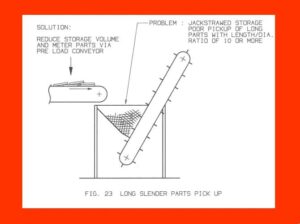
- Handling Long Parts (Figure 23):
- Issue: Long parts can “jackstraw.”
- Solution: Reduce storage volume or use horizontal metering conveyors.
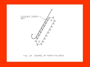
- Flexible Cover Belts (Figure 24):
- Function: Control fall-back and ensure gentle handling.
- Function: Control fall-back and ensure gentle handling.
- Drive Location (Figure 25):
- Optimal Design: Head shaft driven conveyors for better performance and lower costs.
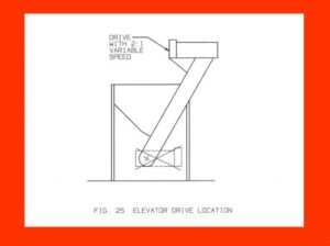
- Optimal Design: Head shaft driven conveyors for better performance and lower costs.
- Gravity Orienting Elevators (Figure 27-28):
- Application: For simple rolling or sliding parts with static tooling.

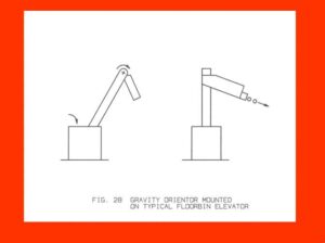
- Application: For simple rolling or sliding parts with static tooling.
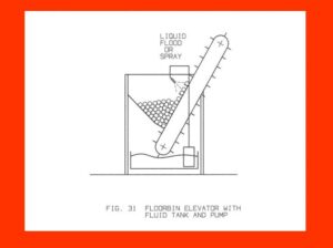
- Fluid Handling (Figure 31):
- Concept: Submerge elevators in tanks or use fluid spraying for quenching, washing, or lubricating.
- Concept: Submerge elevators in tanks or use fluid spraying for quenching, washing, or lubricating.
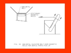
- Magnetic Elevators (Figure 33):
- Feature: Use magnetic rails and belts to handle ferrous parts gently.
- Feature: Use magnetic rails and belts to handle ferrous parts gently.
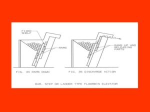
- Ram Elevator Systems (Figure 34-35):
- Concept: Use rams instead of conveyors to elevate parts in stages.

- Concept: Use rams instead of conveyors to elevate parts in stages.
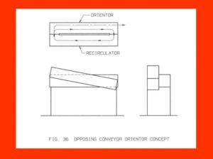
- Rotary and Inclined Chutes (Figure 39-40):
- Function: Gently guide parts into stock boxes or onto conveyors.
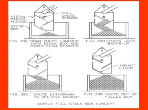
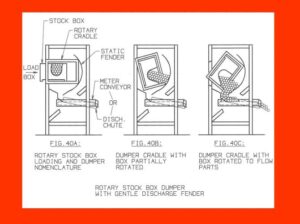
- Function: Gently guide parts into stock boxes or onto conveyors.
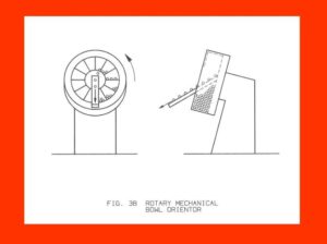
- Vibratory Bowl Feeders (Figure 43):
- Most Popular: Effective for complex shapes and materials, using circular flow to orient parts.
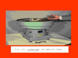
- Most Popular: Effective for complex shapes and materials, using circular flow to orient parts.
- Straightline Vibratory Orientors (Figure 44):
- Technology: Similar principles to bowl feeders, but for linear part movement.
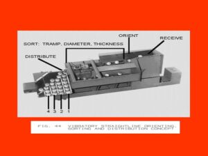
- Technology: Similar principles to bowl feeders, but for linear part movement.